
Split-System Replacement
Standard Split System Replacement: Replacing an Air Handling Unit/ Furnace and condenser equipment with new modern equivalent.
 This is a standard Split System swap, wherein we remove old equipment, replace with the modern equivalent. We will connect to existing power wiring, connect to existing drain systems as needed, and install a new disconnect which will be turned on and test. There are no enhancements to the duct work, new power wiring installations or configurations to existing plumbing systems.
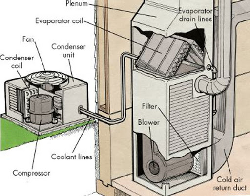
 Definition: A split system has a metal cabinet with the condenser and compressor outdoors, usually on a nearby concrete platform. It also has an indoor air handler that contains a fan and an evaporator coil. In contrast, a packaged unit has just one cabinet for the evaporator coil, condenser, compressor, and most other parts.
Scope of Work
- Perform required lockout/tag out safety protocol as per NFPA70E of all high-voltage electrical circuits prior to beginning work on the existing unit.
- Recover all of the existing refrigerant (Freon) into EPA approved recovery cylinders for safe disposal as per EPA guidelines.
- Provide off-site disposal of job site refuse/debris.
- Demo and dispose of the existing condensing unit in accordance with EPA regulatory guidelines.
- Demo and dispose of the existing air handler or furnace.
- Furnish and install (1) cannister of RX-11 line flush in order to clean the existing copper refrigerant line set.
- Furnish and install (1) 4oz bottle of Acid-away acidic neutralizer.
- If required provide crane or material lift for equipment placement at overhead locations.
- Furnish and install new AHU/Furnace.
- Furnish and install new condensing unit.
- Adapt and connect existing supply and return ducting, seal all seams and penetrations with UL rated foil-backed tape and applicable mastic sealant as needed.
- Attach to the existing copper refrigerant tubing, controls and electrical power wiring.
- Pressure test to 250 psi with dry nitrogen to ensure all newly soldered copper connections are leak free prior to evacuation.
- Evacuate system to 500 microns as per EPA industry regulatory guidelines.
- Confirm voltage prior to testing.
- Perform basic start-up and testing to ensure proper operation prior to departure and adjust refrigerant charge according to manufacturer’s recommendations. Depending on outside ambient air temperature at the time of system install, this may require a return trip in the future to further balance the charge to ideal specifications as listed by the nomenclature on the unit’s data tag.
- Adjust superheat and sub-cooling values to reflect the manufacturer’s recommendations.
This article has been shared by Direct Service, Construction and Design to specifically accommodate our intended clientele. The intent of sharing this information is to better inform the public of these general topics, expand knowledge and safety for all and provide crucial information in regard to their MEP and building systems and/or assets. It is NOT our recommendation that any article recommendations or how-to scenarios be attempted by anyone other than a qualified or competent person.